- WhatsApp:+86-19892834301
- Email: automantool@hotmail.com
- Skype:autoobdtop
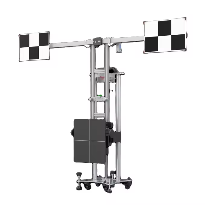
SmartSafe X-431 X431 ADAS LITE ADAS Calibration Machine
0 out of 50 global ratings
- 5 stars:0%
- 4 stars:0%
- 3 stars:0%
- 2 stars:0%
- 1 stars:0%
ratings| answered questions
0 global ratings
- 5 stars:0%
- 4 stars:0%
- 3 stars:0%
- 2 stars:0%
- 1 stars:0%
Fast Shipping & No Tax
US Check: Ship from US
UK Check: Ship from UK
EU Check: Ship from Czech
Looking for help? Please contact Whatsapp: +86-19892834301
- X431 ADAS Lite Configuration
- Shipping:
-
Free Shipping
Express Shipping ServiceEstimated delivery time: 3-5 Working Days
- Quantity:
- Stock:59
- Weight:
- 69 KG
- Package:
Related Download Files
SmartSafe X-431 ADAS LITE ADAS Calibration Machine
Notes: When you place an order, it defaults to the basic version. there are other accessories for selection. if you need other accessories, please contact us further
X-431 ADAS LITE is a foldable, portable and lightweight ADAS calibration machine. It is used to calibrate front and rear cameras and radar sensors. Suitable for multiple ADAS system calibrations , and compatible with and targets. Working better with X-431 ADAS PRO PLUS and X-431 ADAS Mobile targets. Working together with iSmartLink D01 or iSmartLink 801
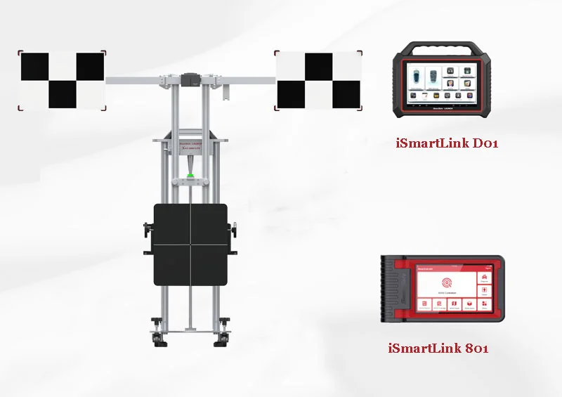
Features
*Simple structure design, portable and free movement of the whole machine, shared by multiple calibration stations
*Supports multiple ADAS system calibrations, and covers many Euro-American and Asian brand models, with super high-cost performance
*Support LDW/ACC/AVM/NVS/BSD/RCW ADAS system calibration
*Quick centering and parallel, new centering and parallel method, simple and efficient in the whole process
*The cross beam can be folded on both sides to take up less space
*Compatible with ADAS Mobile & PRO+ targets
*The newly upgraded aluminum alloy material is durable
Functions
What Can Be Solved in Your Shop
X-431 ADAS LITE is an ultra-high-precision professional ADAS calibration equipment, which can meet multi-system and multi-station calibration at the same time, and provide more comprehensive ADAS calibration services for repair shops.
| Functions | Description | √ |
Multi-System Calibration | √ | |
Multi-Vehicle Model Calibration | Supports ADAS system calibration for over 90 vehicle brands in Europe, Americas, Asia, and China, with over 90 target models | √ |
Device Folding | Supports beam folding | √ |
Device Elevation | Supports manual elevation adjustment, using a laser rangefinder for height positioning | √ |
Parallel Alignment | Achieves device parallel alignment using auxiliary accessories like alignment assist lines | √ |
Level Adjustment | Observe the bubble level, adjust the base knob, and achieve device leveling | √ |
*LDW: Land Departure Warning
*AVM: Around View Monitor
*ACC: Adaptive Cruise Control
*BSD: Blind Spot Detection
*RCW: Rear Collison Warning
*NV: Night Vision
Vehicle Coverage:
| European | |||||||
|---|---|---|---|---|---|---|---|
| Mercedes-Benz | BMW | Audi | Volkswagen | Land Rover | Jaguar | Volvo | Fiat |
| Opel | Seat | Skoda | Renault | Citrone | Smart | Mini | Peugeot |
| Porsche | Romeo | ||||||
| Asian | |||||||
| Kia | Hyundai | Toyota | Lexus | Honda | Acura | Nissan | Infiniti |
| Mitsubishi | Subaru | Suzuki | Daihatsu | Mazda | JAC | SGMW | Baic |
| BYD | Haval | Chery | Lynk&Co | ||||
| American | |||||||
| GM | Ford | Chrysler | Buick | Cadilac | Chevrolet | Dodge | Jeep |
| Lincoln | |||||||
SmartSafe X431 ADAS Lite Accessories:
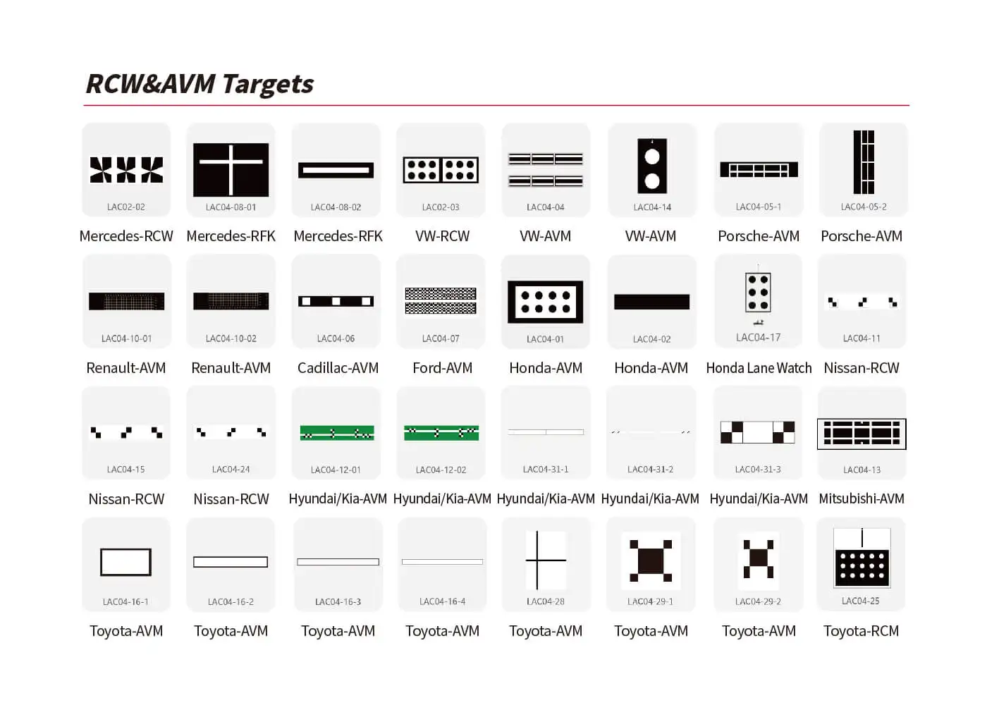
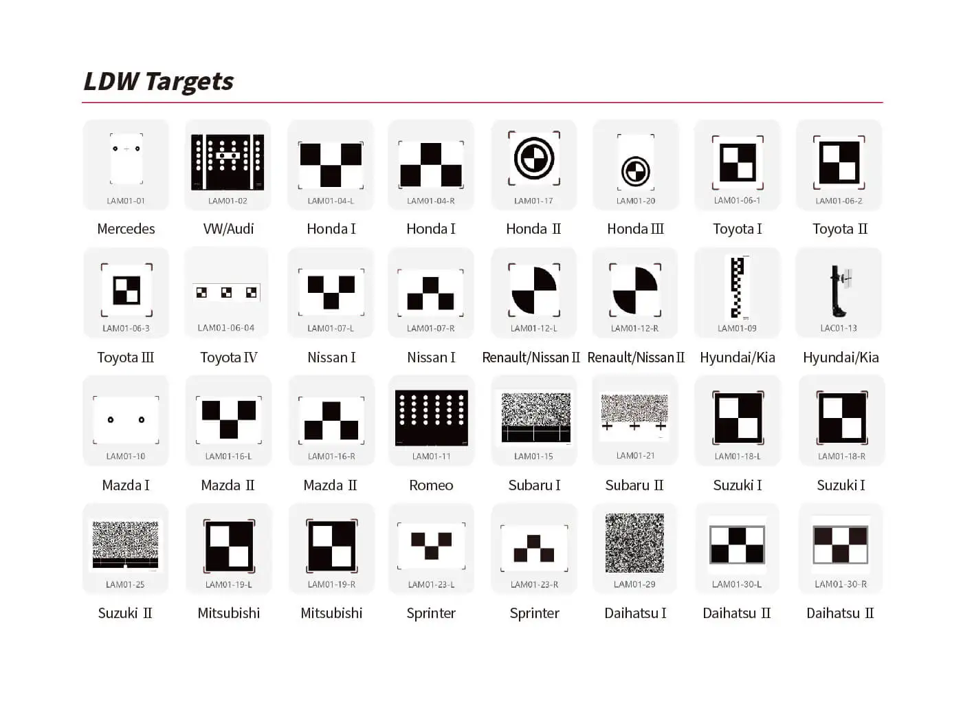
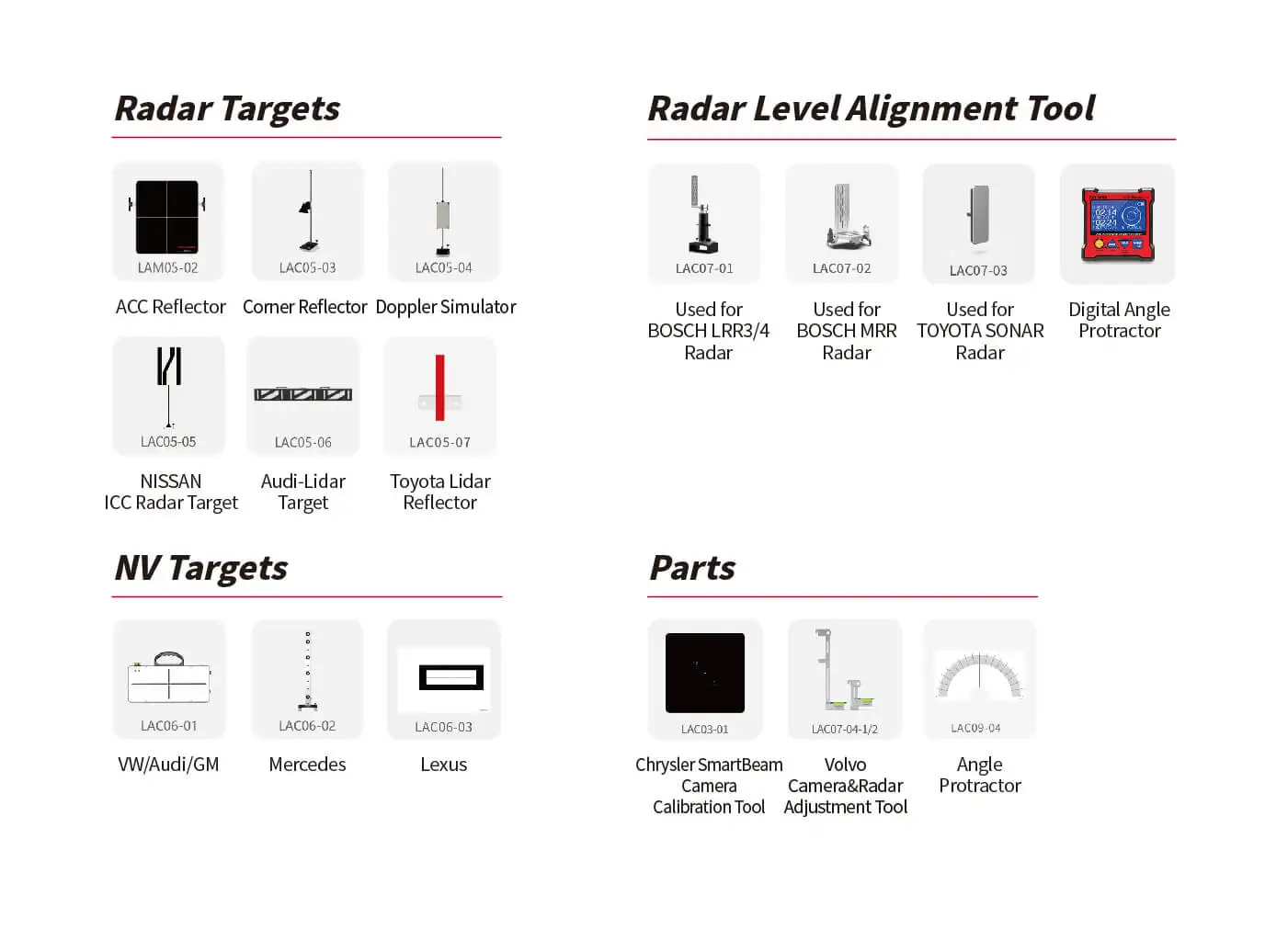
How to Choose ADAS Calibration Targets, factors to consider are:
① Vehicle type: confirm your brand and model
② Calibration types and space required by the target
③ Target cost: some targets are expensive and need to be factored into your decision-making
④ Shop conditions: workstation size, workstation lighting, workstation floors
By considering these factors, you will be able to make more favorable choices about how to select your ADAS targets!
With its powerful calibration function and low price, X-431 ADAS LITE becomes the most cost-effective choice for automotive. With its powerful calibration function and low price, X-431 ADAS LITE becomes the most cost-effective choice for automotive.
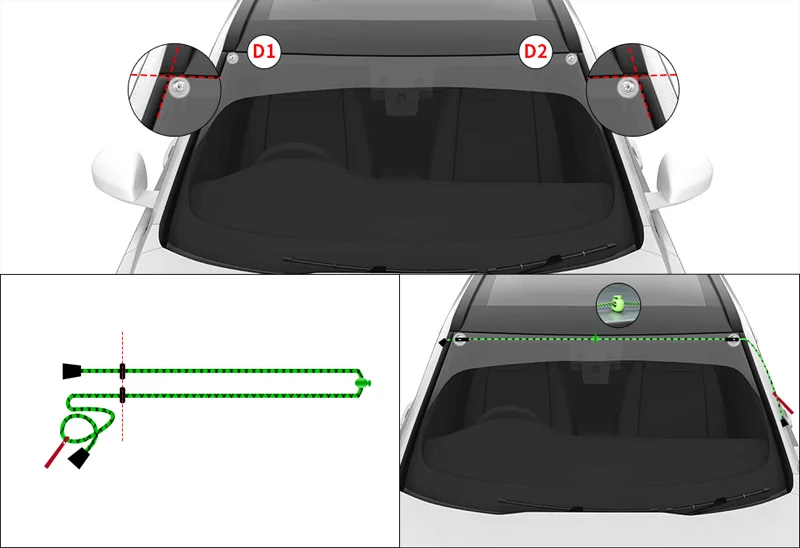
Step 1: Confirm the vehicle alignment reference point
First, use suction cups to mark point D1 and point D2 on the upper left corner and upper right corner of the front windshield of the vehicle respectively.
Second, use the centering auxiliary line to align the symmetrical points at both ends.
Thirdly, remove the centering auxiliary line and fold the two ends in half.
Fourth, move the centering reference point to the center of the auxiliary line, and reposition the alignment and positioning auxiliary line at point D1 and point D2.
Note: It is necessary to keep the wire harness in a tightened state when positioning the centering auxiliary line.
Step 2: Confirm the location of the equipment
According to different models, it is divided into the following three situations.
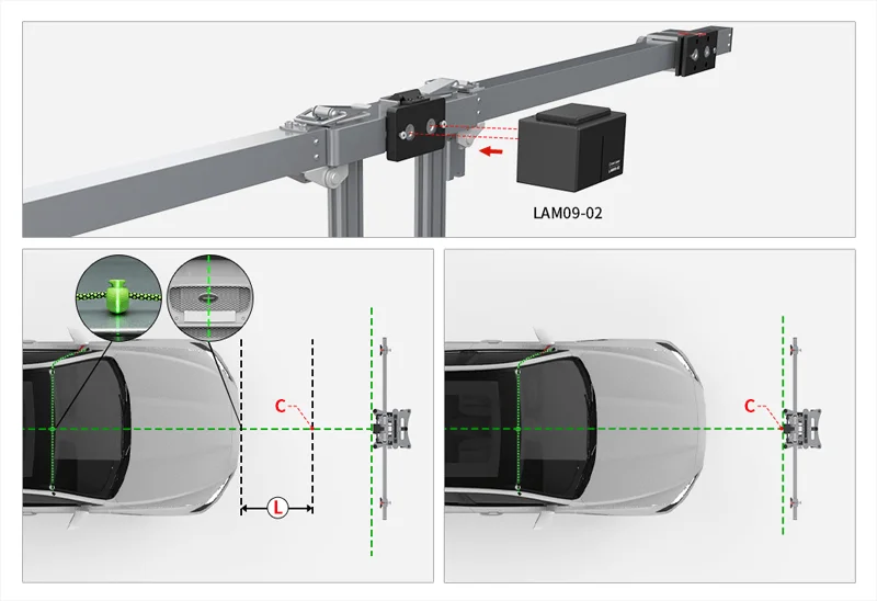
The measurement target is placed on the front bumper
1. Install and open cross laser LAM09-02.
2. Move the device to the front of the vehicle so that the longitudinal laser line of the cross laser device LAM09-02 passes through the center of the vehicle logo and the centering mark on the roof respectively. Place a cross-positioning mark on its longitudinal laser line, marking point C, so that the distance from the front bumper of the vehicle to point C is L, L=_______mm.
3. Move the device so that the laser intersection point of the cross-laser instrument LAM09-02 coincides with point C. The longitudinal laser line passes through the center of the vehicle logo and the centering mark on the roof respectively.
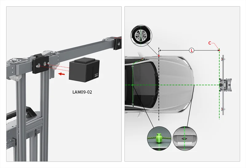
The measurement target is placed in the center of the front hub
1. Place the L-shaped positioning bracket LAM09-05 at the center of the front hub of the vehicle.
2. Measure the distance from the center of the front wheel to the target as L, L=_______mm, place a cross-positioning marker, and mark point C.
3. Install and switch on the cross laser LAM09-02.
4. Move the device so that the horizontal laser line of the cross laser LAM09-02 passes through point C, and the vertical laser line passes through the center of the vehicle logo and the centering mark respectively.
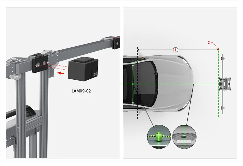
The measurement target is placed in the center of the front camera
1. Place the L-shaped positioning bracket LAM09-05 on the side of the vehicle to align it with the camera.
2. Measure the distance from the center of the front camera to the target as L, L=_______mm, place a cross-positioning marker, and mark point C.
3. Install and switch on the cross laser LAM09-02.
4. Move the device so that the horizontal laser line of the cross laser LAM09-02 passes through point C, and the vertical laser line passes through the center of the vehicle logo and the centering mark on the roof respectively.
Step 3: Adjust the Equipment Level
1. Adjust the base knob ① so that the horizontal bubble ② is located in the center area.
2. Confirm again that the longitudinal laser line passes through the center of the vehicle logo and the alignment reference point respectively, and the distance L between the equipment and the vehicle remains unchanged.
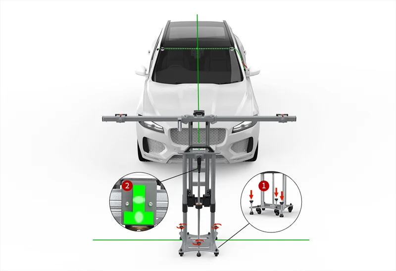
Step 4: Install the target and adjust the height of the equipment
1. Turn off the cross laser LAM09-02 and remove it.
2. Use the LAM01-XX target, align the groove at the bottom of the target with the locking position of the support bar, and lock and fix the target through the left and right sliders.
3. Adjust the height of the equipment and observe the electronic range finder, H=_______mm.
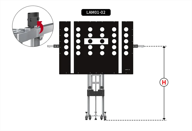
Small target - Situation 1: Single target/single position
1. Turn off the cross laser LAM09-02 and remove it.
2. Use the LAM01-XX target, and install the target on the center mounting plate.
3. Adjust the height of the equipment and observe the electronic range finder, H=_______.
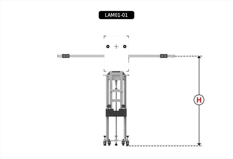
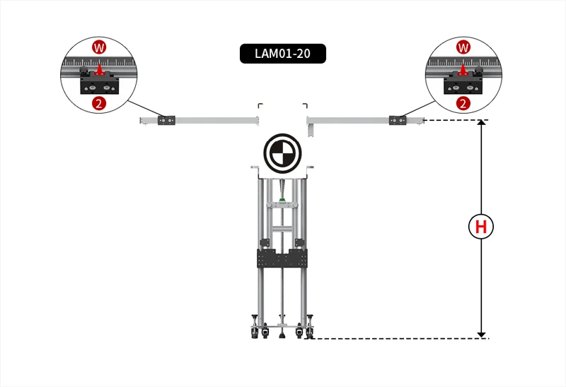
Small Targets - Situation 2: Multiple targets/multiple positions
1. Turn off the cross laser LAM09-02 and remove it.
2. Move the left and right slider ② to position W, W=_______.
3. Use the target LAM01-XX and LAM01-XX, and install the target on the left and right sliders ②.
4. Adjust the height of the equipment and observe the electronic range finder, H=_______.
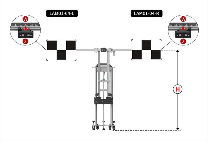
Small Target - Situation3: Single Target/Multiple Positions
1. Turn off the cross laser LAM09-02 and remove it.
2. Move the left and right slider ② to position W, W=______.
3. Use a LAM01-XX target, and install the target on the center mounting plate.
4. Adjust the height of the equipment and observe the electronic range finder, H=_______.
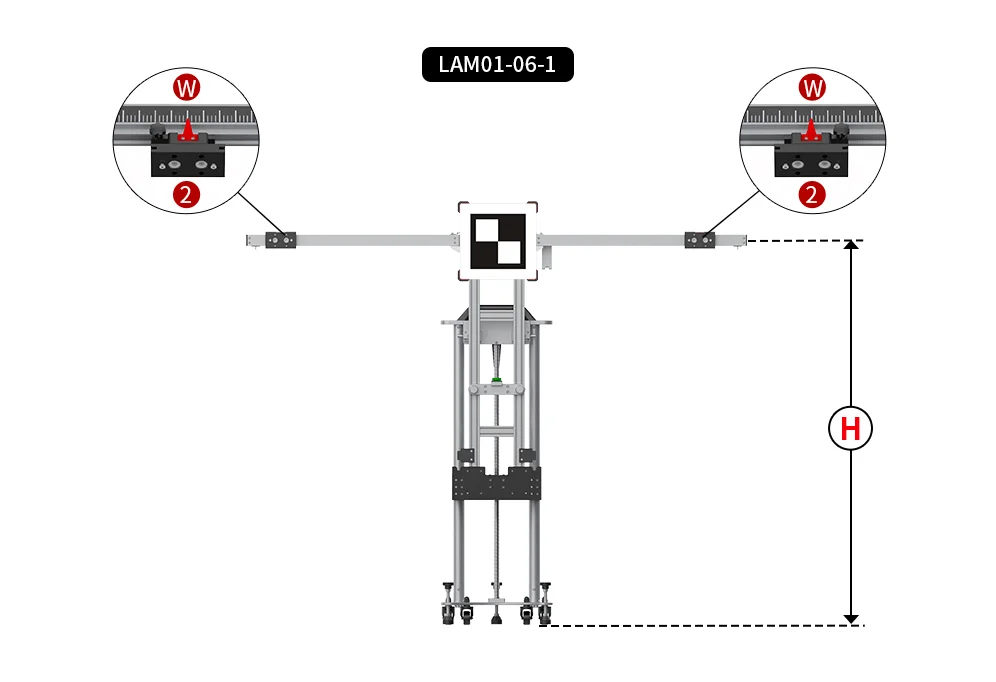
Install the target switch onto the left slide.
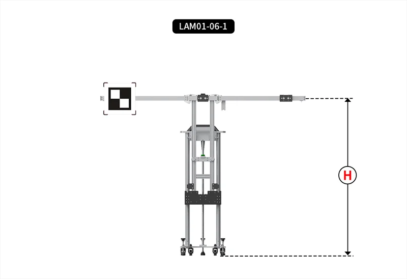
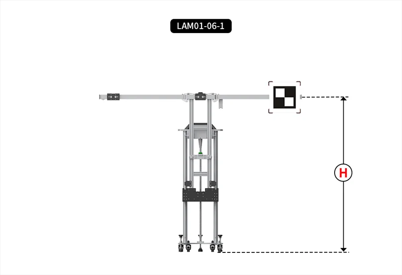
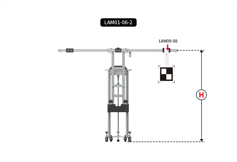
Small Target - Situation 4: Single Target/Multiple Positions - Extension Pole Mode
1. Turn off the cross laser LAM09-02 and remove it.
2. Move the left and right slider ② to position W, W=_______.
3. Use the LAM01-XX target, install the target on the extension pole LAM09-08, and hang it on the middle hanging plate.
4. Adjust the height of the equipment and observe the electronic range finder, H=_______.
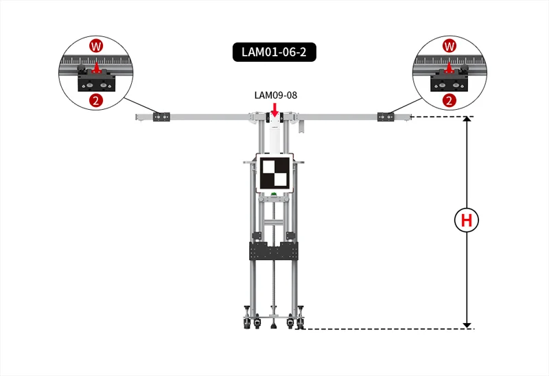
Install the target switch onto the left slide.
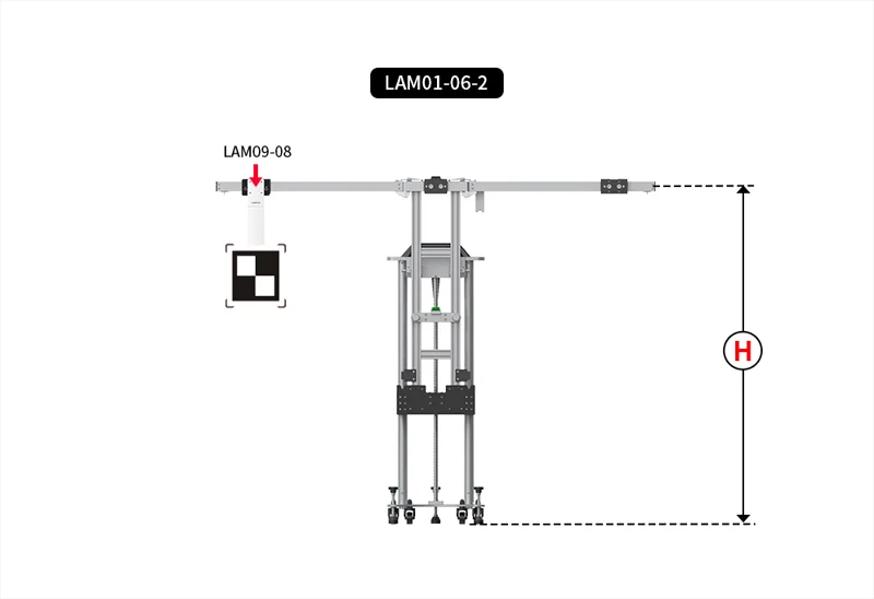
Install the target switch onto the right slide.
Small Target - Situation 5: Single Target/Multiple Positions - Extension Pole Mode
1. Turn off the cross laser LAM09-02 and remove it.
2. Move the left and right slider ② to position W, W=_______.
3. Use a LAM01-XX target, and install the target on the center mounting plate.
4. Adjust the height of the equipment and observe the electronic range finder, H=_______.
Install the target on the extension pole LAM09-09, and hang it on the left slider.
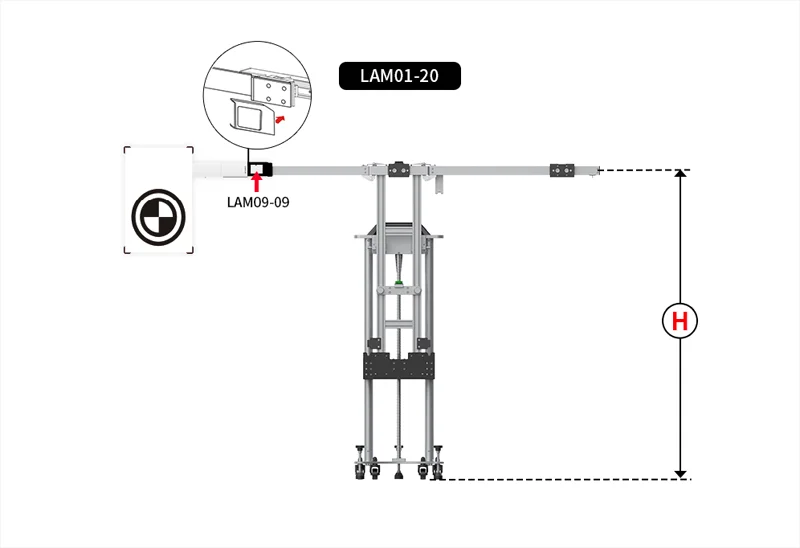
Install the target on the extension rod LAM09-09, and hang it on the right slider.
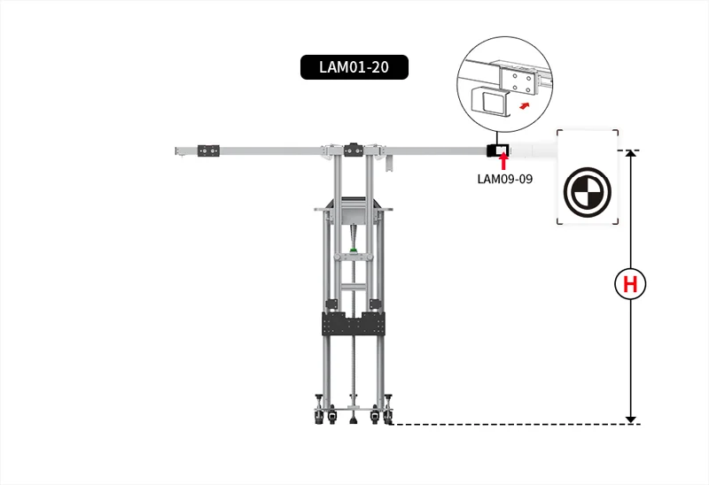
Step 5: Start Calibration
0 Stars of 5,0 Reviews.
- 5 stars:0%
- 4 stars:0%
- 3 stars:0%
- 2 stars:0%
- 1 stars:0%
Share your thoughts with other customers.
Write a reviewYou may also like
-
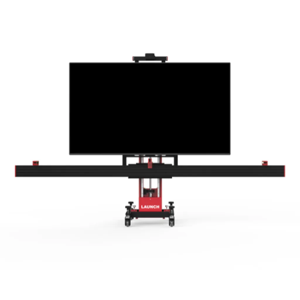
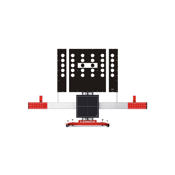
X-431 ADAS PRO Calibration Tool
$4939.001% off
-
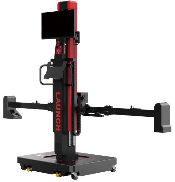
Newest 3D wheel aligner no beam no calibration FCAR FD-305 portable aligner wheel alignment machine garage equipment and tools
$4159.002% off

-
New Launch CNC-603C CNC603C Ultrasonic Fuel Injector Tester & Cleaner 6 Cylinders English Panel For Gasonline Car
$499.007% off
-
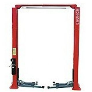
TLT240SCA Clear Floor Two Post Lift
$1580.003% off
-
Tel
+86-19892834301 -
WhatsApp


