- WhatsApp:+86-19892834301
- Email: automantool@hotmail.com
- Skype:autoobdtop
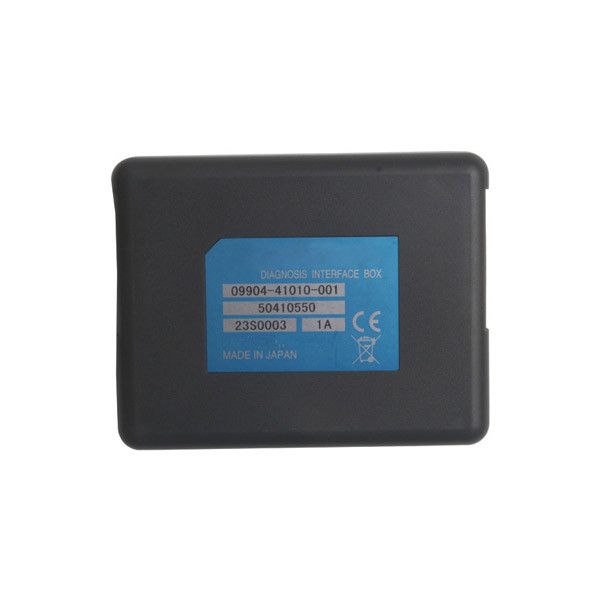
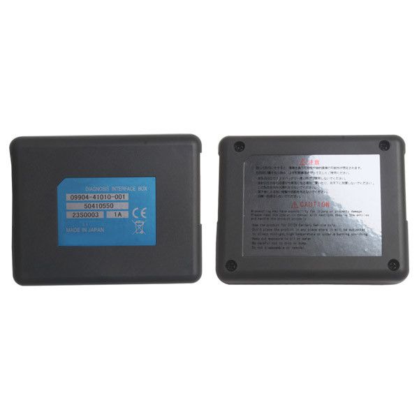
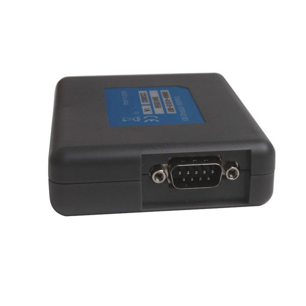
SDS For Suzuki Motocycle Diagnosis System
Item No. P210
In Stock.
History sold.
0 out of 50 global ratings
- 5 stars:0%
- 4 stars:0%
- 3 stars:0%
- 2 stars:0%
- 1 stars:0%
ratings| answered questions
0 out of 5
0 global ratings
- 5 stars:0%
- 4 stars:0%
- 3 stars:0%
- 2 stars:0%
- 1 stars:0%
Latest price:$158.00
Buy Now:
$
148.00
6% off
Fast Shipping & No Tax
US Check: Ship from US
UK Check: Ship from UK
EU Check: Ship from Czech
Looking for help? Please contact Whatsapp: +86-19892834301
- Shipping:
-
Free Shipping
Express Shipping ServiceEstimated delivery time: 3-5 Working Days
- Quantity:
- Stock:5
- Weight:
- 0.4 KG
- Package:
Related Download Files
Share
SDS For Suzuki Motocycle Diagnosis System
Top 3
Reasons to Get SDS
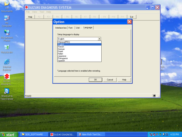
1. Languages: French,English,German,Italian,Spanish,Greek,Portuguese,Japanese,Chinese
2.
Operating System: Windows XP, Vista and 7
3. Support Year: 2000-2012
Notice: SDS Cannot Be Updated
Specifications and
Functions
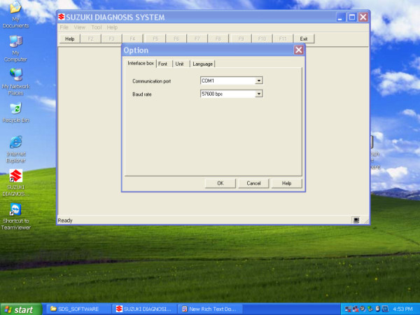
(1) This system diagnoses trouble by communicating
with the onboard computer using specially designed software that operates on
commercially available Windows 95, 98, 2000, XP, Vista and 7, the special
interface box that translates/converts the computer communication signals, and
the special communication cable.
(2) Taking application in motorcycles into
consideration, the interface box has been made compact and light in weight. In
addition to providing a connector to the vehicle, the system is equipped with
two types of connector, USB and RS-232C, for communication with the computer so
as to be compatible with both new and old computers.
(3) The interface box is not waterproof because
standardized connectors are used. The operabletemperature range is 0 – 50 °C.
The maximum vibration resistance is 2.2G, which requires protection from impact
and vibration.
(4) For communication protocol between the computer
and adaptor, the international standard ISO14230 is
used.
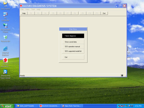
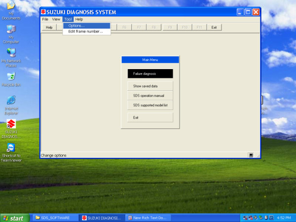
(5) This special software is compatible with nine
languages
(6) Whether the engine is operating or at halt, the
data received from various sensors can be displayed in real time or can be
plotted. The data or graphs displayed can be saved and
printed.
(7) The type of data to be displayed can be
selected.
(8) The saved data can be re-displayed and plotted in
the graph.
(9) The failure code (both past and current) that has
been memorized at the time of failure can be called back and displayed. The
change of data record at the time of failure (2 cases maximum) can also be
displayed.
(10) A"trigger" can be set up for the diagnostic
data. The trigger is a function that starts recording the data from where the
set value is exceeded (or comes short) for one or more data. This function can
also record the timing to display the trouble code in the monitoring
graph.
(11) Active control is possible (such as secondary
air solenoid drive, etc.).
(12) The system can record the data of about 30
minutes of operation as well as driving data. They can be read out and
verified.
(13) The system requires setting up an additional
function to the onboard ECU and use of a special connector. The diagnosis system
is applicable to the new models produced in and after May 2002 (AN 650 onward)
and their model changes. This system is not applicable to those models that were
produced earlier than the above.
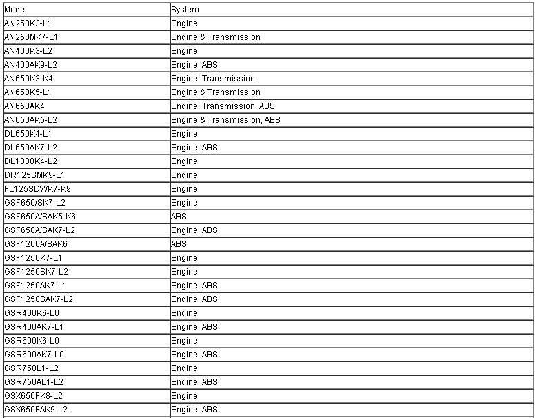
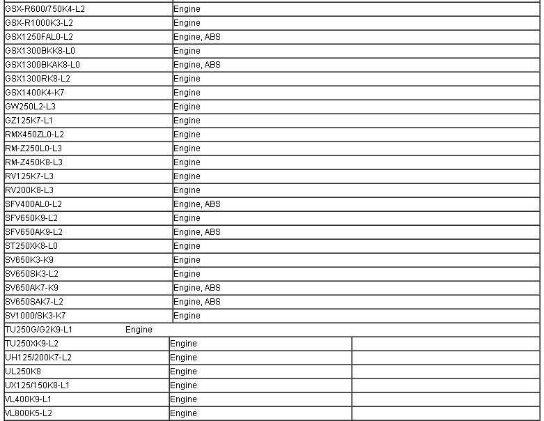
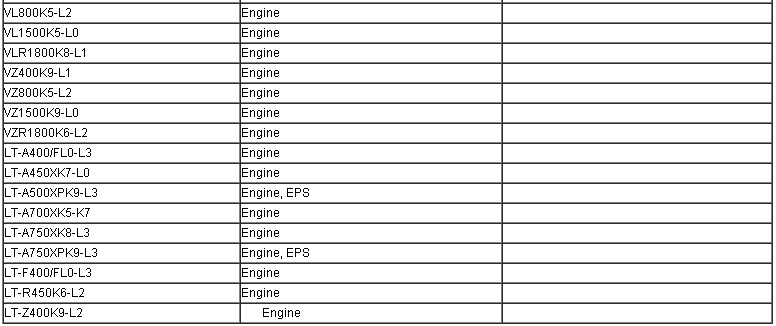
Support Mode and System

Failure Diagnosis
Menu
Data Monitor: Shows the present vehicle condition
using a numerical or graph display.
Executes "Data monitor".
DTC inspection : Shows diagnostic trouble codes saved
in ECU.
Executes "DTC inspection".
Show failure data : Shows the vehicle condition
before and after failure using a numerical display.
Executes "Show failure
data".
Active control: Controls the vehicle temporarily from
the computer.
Enables confirmation of the
system.
Executes the "Active control
menu".
Package list:
1pc x Main Unit
1pc x K-line Cable
1pc x USB Cable
1pc x CD
Customer Questions & Answers
Customer Reviews
0 Stars of 5,0 Reviews.
- 5 stars:0%
- 4 stars:0%
- 3 stars:0%
- 2 stars:0%
- 1 stars:0%
Share your thoughts with other customers.
Write a reviewTop customer reviews
You may also like

-
2025 New JDiag M300 Motorcycle Diagnostic Scanner Helps the Technician to Diagnose Problems and Make Repairs Faster M100PRO M200
$289.006% off
-
SmartTool Motorcycle Diagnostic Tools Smart Key Programmer Programming Machine & ODO Correction
$599.003% off
-
MST-3000pro update MST 3000 Motorcycle Electronic Diagnostic Tool MotorBike ECU Scanner For Asian Motorcycle
$679.003% off
-
MST-500 PRO MST500 PRO Handheld Motorcycle Diagnostic Scanner MST-500 Plus motorbike Brand EFI Diagnostic Tool
$369.0010% off
-
Ighost001 Autobike Scanner Motorcycle Scanner Universal Motor Scan Tool ECU Program Tool Motorcycle DTC Read Equipment
$1389.005% off
-
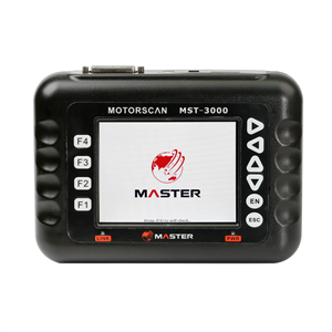
Master MST-3000 Southeast Asian Version/Taiwan Version Universal Motorcycle Scanner Fault Code Scanner for Motorcycle
$659.006% off
-
Tel
+86-19892834301 -
WhatsApp


