- WhatsApp:+86-19892834301
- Email: automantool@hotmail.com
- Skype:autoobdtop
MDVCI Maserati Detector SD3 Support Diagnosis with Maintenance Data Installed on Panasonic CF19 Ready to Use
0 out of 50 global ratings
- 5 stars:0%
- 4 stars:0%
- 3 stars:0%
- 2 stars:0%
- 1 stars:0%
ratings| answered questions
0 global ratings
- 5 stars:0%
- 4 stars:0%
- 3 stars:0%
- 2 stars:0%
- 1 stars:0%
Fast Shipping & No Tax
US Check: Ship from US
UK Check: Ship from UK
EU Check: Ship from Czech
Looking for help? Please contact Whatsapp: +86-19892834301
- Shipping:
-
Free Shipping
Express Shipping ServiceEstimated delivery time: 3-5 Working Days
- Quantity:
- Stock:35
- Weight:
- 7.5 KG
- Package:
Related Download Files
MDVCI Maserati Detector SD3 Support Diagnosis with Maintenance Data Installed on Panasonic CF19 Ready to Use
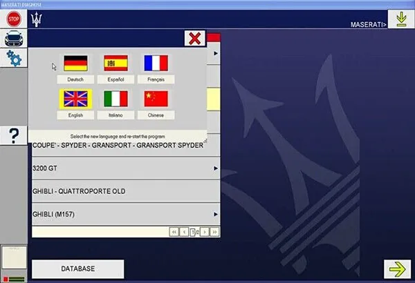
SD3 diagnostics tool Languages: English, French, Spanish, German, Italian

SD3 Diagnostic Scanner for Maserati Description:
SD3 Diagnostics System is an electronic device for the diagnostics of electronic control units (ECU) installed in all modern vehicles.
The SD3 diagnostics tool operates on a palmtop device with a backlit color LCD display and a membrane keypad with twenty keys
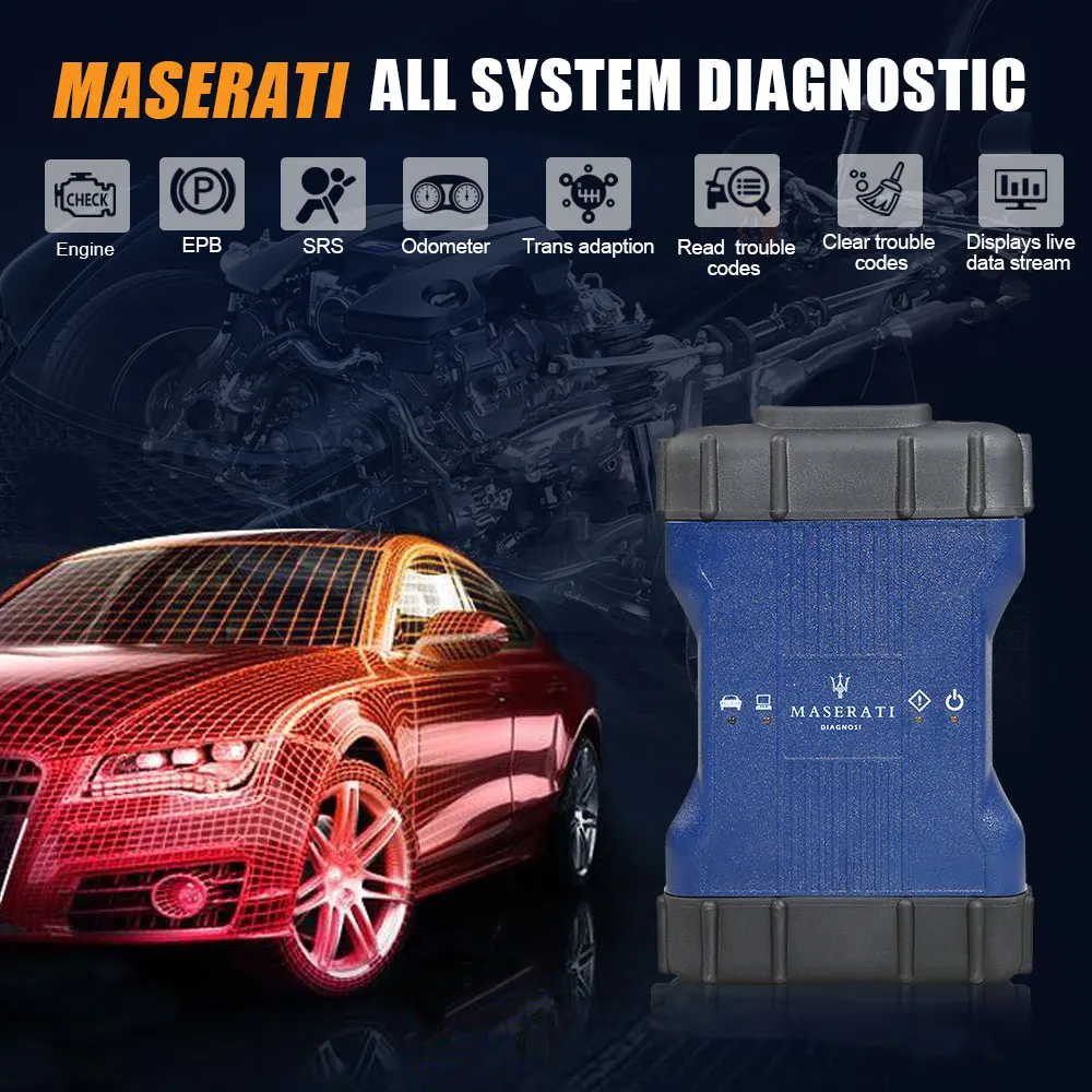
The MDVCI of Maserati Diagnostics System is an electronic device for the diagnostics of electronic control units(ECU) installed in modern vehicles. It's cover Maserati from 1995 year(Ghibli and Quattroporte)3200GT,4200 from MY2002-MY2006,Qauttroporte and gran tourismo from 2004 till 2016.

Maserati SD3 Function Characteristics:
Built-in system
Diagnostic assistance
Maintenance manual
Circuit diagram
Parts Query
Labor Hours Query
Maserati SD3 Diagnostic System Support Model:
Cover SD2 / SD3 Until 2016
3200 GT (3200 GT)
Ghibli (M157)
Gransport (Gransport)
GranTurismo (M145)
GT (M138)
Quattroporte (M139)
Quattroporte (M156)
Quattroporte MY (M139 MY)
Note: Doesn't Support SUV LEVANTE and Grecale
The New maserati
diagnostic tester system is a Panasoinc CF laptop device.It is also equipped
with:
Standard RS232C
serial lines x 3
Standard ISO9141 /
CARB / KEYWORD 2000 serial lines x 6
Standard CAN serial
lines x 2
Multimeter in volts
(up to 200 V d.c.) and Ohm (up to 1 Mohm)
Maserati Diagnosi
Tester can be interfaced to a PC containing the software required to update the
ECU diagnostics software throughone of the following lines:
Standard RS232C
serial line
USB serial
line
Ethernet 10/100Mbit
network
Ethernet Wireless
802.11b network
For better
efficiency and faster data transfer between the PC and the DEIS unit, we suggest
you use the USB line or an Ethernet/Wireless network for
communications.
Suitcase
contents
The SD3 diagnostics
tool is supplied with a suitcase containing:
1.SD3
Tester;
2.Serial cable for
SD3/SD2 connection to PC (SD3-CBL01) [095970327];
3.Multimeter cable
(SD3-CBL02) [095970328];
4.Power supply
feeder (SD3-CBL05) [095970331];
5.EOBD SD3 diagnosis
cable (SD3-CBL06) [095970332];
6.Diagnosis cable
with SD2 bridle (SD3-CBL07) [095970333];
7.Connection cable
for feeding among SD2 and SD3 bridle (SD3-CBL08) [095970334];
8.Cigar lighter
socket feeder (SD3-CBL09) [095970335];
9.ISO 1 extension
(SD3-CBL10) [095970336];
10.ISO 2 extension
(SD3-CBL11) [095970337];
11.SD2 B-CAN adapter
(SD3-CBL12);
12.USB cable
[095970330];
13.10/100 Mbps
Ethernet cross-over cable [095970329];
14.SD3 wireless
board;
15.SD3 Manual
[095970324];
16.SD3 Quick
Reference;
17.Installation
CD-ROM [095970326];
18.8 metal-point
rods for Multimeter.
19.PC USB/Wireless
board
SD3 diagnostics tool
presentation
The SD3 Diagnostics
System is an electronic device for the diagnostics of electronic control
units(ECU) installed in modern vehicles.
The SD3 diagnostics
system is a palmtop device with a backlit color LCD display and a membrane
keypad with twenty keys; it is also equipped with:
· three standard
RS232C serial lines;
· six standard
ISO9141 / CARB / KEYWORD 2000 serial lines;
· two standard CAN
serial lines
· multimeter in
volts (up to 200 V d.c.) and Ohm (up to 1 Mohm)
It can be interfaced
to a PC containing the software required to update the ECU diagnostics software
through one of the following lines:
· standard RS232C
serial line,
· USB serial
line
· Ethernet
10/100Mbit network
· Ethernet Wireless
802.11b network
For better
efficiency and faster data transfer between the PC and the SD3 unit, we suggest
you use the USB line or an Ethernet/Wireless network for
communications.
Warning, the SD3
Tester keypad can be used as remote control for the PC software for all
communications lines except the serial lines.
SD2
Emulator
The SD3 diagnostics
tool can be used with SD2 Diagnostics software in the emulator mode.
The latter must be
transferred to the SD3 tester through the basic SD3NET software and using the
special SD2 Porting CD (Never use the old
SD2 CD).
If you wish to run
diagnostics in STANDALONE mode, follow the old SD2 instructions.
If, instead, you
wish to run diagnostics using the SD2 software on the PC, you must first press
the "START SD2 EMULATOR
COMMUNICATIONS" button on the SD3 tester.
Be careful because
in this mode, the only communications line possible between the PC and the SD3
is the RS232C serial line.
Multimeter
The SD3 Diagnostics
System has an integrated multimeter that can take measurements in Volts (up to
200 V dc) and Ohms (up to 1 Mohm). This function can be selected from the SD3
Tester main menu.
Scantool
OBD
The SD3 diagnostics
tool has an integrated Standard Scantool OBD software. This system makes it
possible to automatically check for systems able to support the service (engine,
shift, ...). Once the control unit has been identified by the software, you can
check some parameters/errors supplied by the system itself.
This function can be
selected from the SD3 Tester main menu.
Power supply
voltage
The SD3 requires a
voltage between 8 and 16 V DC which is supplied either by the battery of the
vehicle being tested or by the power supply provided with the
product.
Installation
instructions for the SD3
The SD3 diagnostics
tool does not require any installation; it only needs to be configured with the
diagnostics software to be used. The downloaded software are stored in the
non-volatile memory of the SD3 unit.
The SD3 is equipped
with a battery-powered clock which can be set and checked on the PC through a
special software menu.
General
Description
The figures below
provide a diagram of the upper part (containing the power supply and diagnostics
connectors), front part of the SD3 unit (containing the display, keypad and ON
light) and the lower part (containing a flap which provides access to the
connectors used to hook up an American PS2 keyboard for the PC, and two PCMCIA
connectors used for any hardware expansions-e.g. flash expansions, Wireless
card-through external boxes).
The ten keys at the
bottom of the screen are used to input data (numbers/letters) into the
diagnostics software.
The directional
arrows and the TAB key feature function repetition if the key is held down
continuously.
In all menus, hold
down "Switch" and "Esc" for 4 seconds to reset the SD3 Tester software. This
speeds up restarting the device if the software crashes (the Tester does not
respond to keypad commands).
The top holds the
following :
1.The power
button.
2.One 25-pin
connector for power and serial diagnostics lines (on the power button
side);
3.One 9-pin
connector (male) for hook up to the PC (in the centre);
4.One 9-pin
connector (female) for Multimeter inlet.
5.One Ethernet
10/100 Mbit connector.
6.One USB
connector.
7.One Connector to
hook up a CRT VGA monitor
Software figures
shown as follows:


1pc x The Host
1pc x USB Cable
1pc x The power supply
0 Stars of 5,0 Reviews.
- 5 stars:0%
- 4 stars:0%
- 3 stars:0%
- 2 stars:0%
- 1 stars:0%
Share your thoughts with other customers.
Write a reviewYou may also like

-
V2025.05 BMW ICOM Next BMW ICOM A3 Support WiFi BMW Professional Diagnostic Tool Auto Scanner
$356.004% off

-
Can Clip V240 for Renault vci3 RE VCI3 1:1 Original Drivers OBD2 Programming RE-VCI3 for R-enault Auto Diagnostic Tool 1994-2025
$149.0012% off

-
Newest VAS6154 6154A Support DOIP Protocol For VAG Car Diagnostic Tool Programming Interface Newest Odis Software V23.01
$229.008% off

-
SVCI V2020 Full Version IMMO Diagnostic Programming Tool with 22 Latest Software All VAG Special Functions Activated
$539.004% off
-
Tel
+86-19892834301 -
WhatsApp


